|
Send E-mail |
In a second installment after having added Vickers' own progress reports on the development of the VC10 to this website, I have now created these pages which pay tribute to the development of the VC10 50 years ago. The recollections below and on the subsequent pages were written recently by Maurice Ungless, at the time of writing 73 years of age, who felt that this was the right time to look back on his years with Vickers Armstrongs at Weybridge and Wisley. During his time there he was involved with the VC10's development as a ground crew member, which took him to many locations around the globe and even across the equator!
The story of my relation to the VC10 begins around August 1959, when as an apprentice at Vickers Armstrongs (Aircraft) Weybridge I was attached to the Tool Room Inspection Department, which saw me taking part in the initial construction alignment checks of a VC10 fuselage sub-assembly jig. Before this, from January 1958 to December 1958 I had been involved in the construction of the first Vickers Vanguard G-AOYW. I ended my apprenticeship at Wisley at 22nd August 1960, but stayed there as Aircraft Ground Crew Technician on Vanguard development trials, until circa August/September 1961. I was then re-deployed to Weybridge for the construction of the first VC10 G-ARTA, which started in Weybridge Assembly Line Hangar W1, the location now of which is a housing estate, Staniland Drive/Dixon Drive area of Brooklands Weybridge. Historians may be interested in the fact that this Assembly Line Hangar also housed the construction line for amongst other types: Vickers Wellington Bombers, Vickers Vikings, all of the Vickers Valiant Bombers, some of the Vickers Viscounts, all of the Vickers Vanguards, most of the VC10s and some of the BAC 1-11s. With regard to the VC10 construction, only the fuselage and wing join up was carried out in W1 and some internal equipment was installed during this period, the hangar roof being too low to install the fin, rudder and tail plane. On completion of the VC10 fuselage structure in B1 assembly hangar, on the Oyster Lane side of Brooklands (West Side), the fuselage would be transported on its transportation cradle, across the airfield to the W1 aircraft production line to have the wings fitted. During this process of transporting the completed VC10 fuselage from B1 to W1, the assembly was temporarily parked on a concrete hard standing adjacent to the River Wey, where previous aircraft types, Viscount, Valiant and Vanguard, had their engine ground runs carried out prior to their first flights. The purpose of this temporary halt in transportation was to carry out a pressure and leak test of the fuselage structure to a proof pressure of something like 10.5 psi. On satisfactory completion of this test, the VC10 fuselage transportation was then recommenced to the W1 production line for the fitting of the wings. The VC10 wings were constructed in W1 Wing Shop, which was located to the rear of the aircraft production lines, at the same location as where the Valiant and Vanguard wings had been constructed, then fitted to those aircraft types on the production lines. At a certain point during their construction the individual aircraft were transferred to the larger assembly hangar commonly known as either "The Abbey" or "Cathedral", where all the final assembly was carried out. Fitting of the fin, rudder, tailplane, engines and undercarriages, and all that had not been installed in W1. All aircraft of whatever type would then cross the river Wey by way of the old Brooklands track at the end of what is now Staniland Drive at the Southern end of Brooklands. Areas of extra concrete were added to the original track for the aircraft to be manoeuvred onto the taxi way, for access to the runway, or ground running engines adjacent to the river Wey in the case of Valiants, Viscounts and Vanguards. This section of track/taxi way can still be seen on Google Maps or Google Earth today. For VC10s and BAC 1-11s, ground runs were always carried out at the North end of the runway, about where the Mercedes Benz buildings are located now. Perhaps a few little known facts will emerge from my story, and experiences. However in any birth, complications and pain can ensue. It was no different for the VC10, some minor and major disasters unfolded..
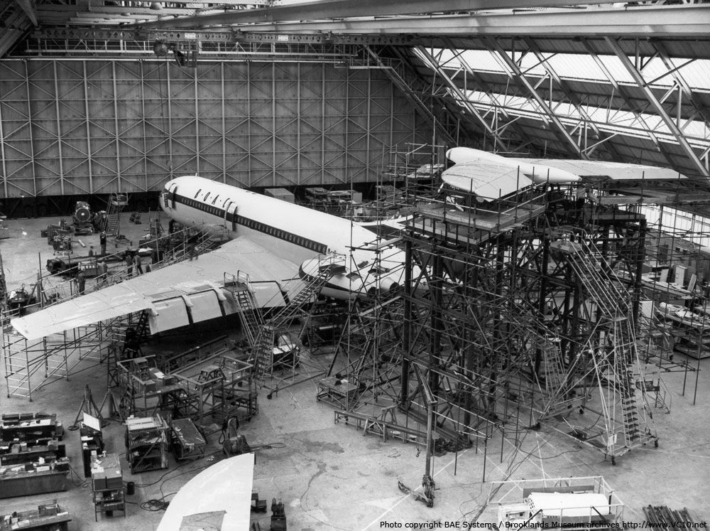
My contribution to the construction of G-ARTA was trial fitting and installing the engine fuel supply pipes, valves and associated shrouds, (where required), from wing trailing edges, in and across the undercarriage bays, and through and above the aft cargo hold to the engines. From these trial fittings and installation, pipe jigs were manufactured for subsequent manufacture of all fuel pipes for the VC10 production. This was the first of a few problems to become apparent in construction. The first production pipes, from aft cargo hold front bulkhead aft, were made by the pipe "benders" from the "lofted drawings" which were full scale drawings on aluminium sheet metal. It was found that the pipes didn't fit the aircraft! Attempts were made several times by the pipe benders, until I noticed that the lofted drawing had the incorrect datum for measurements to be taken from. Once the correct datum was used and new pipes were constructed everything fitted correctly. Also during this period I was involved in fitting the water ballast system which consisted of large water storage tanks and associated pipes, valves and pumps to the forward and aft cargo holds. This system was to allow in-flight adjustment of the aircraft's C of G (Centre of Gravity) during trials, without resorting to landing and physically moving ballast, before another test flight at a different C of G. During this phase of construction the wings were ready to be mated with the centre section of the fuselage and here another problem turned up. On lining up the wing to fuselage abutment joint, the datum point for the wing at the wing tip (a point on the hangar floor) had to be checked with a "plumb bob", this point on the hangar floor having been previously located from drawings and the tool room inspection department alignment checks of the assembly jig. It was found that the wing tip datum was a few inches out, fore and aft, (more or less wing sweep angle). After a few hours of deliberation the design team concluded the datum on the hangar floor was incorrect, and had it replaced to the new position. Another issue turned up when the wing to fuselage abutment joint was aligned as the 4 wing torsion box webs and 4 centre section torsion box webs did not align with each other in the vertical plane. Tapered packers had to be manufactured for alignment of these joints for a satisfactory "no built in stress" construction of the butt joint plates. The wings when ready for assembly to the fuselage centre section were delivered as only a "Torque Box" assembly to the production line. The wing torque boxes were less their leading edges and trailing edge structure, except for aileron attachment frames. After the wing torque box assembly had been assembled to the fuselage centre section and complete, the leading edge structure and trailing edge structure would be fitted. The five large frames located chord-wise across the top surface of the wing shown in the photo on the right are the alignment jigs for five of the six flap beams. The sixth beam is located on the fuselage side and during construction of the fuselage is located by the fuselage jigging. This fuselage integral beam is also shown on the photo above of the VC10 fuselage under leak and proof pressure testing. On completion of this phase of the construction, the aircraft was transported on its mobile fuselage jig cradle to the larger final assembly hangar, the "Cathedral", across the other side of Brooklands adjacent to the railway track, the Oyster Lane side of Brooklands. Here the fin, rudder, tail plane, engines and undercarriages were fitted. By circa April/May of 1962 it was time for the nearly completed aircraft to be lowered from its resting place, which up to that point had consisted of two aircraft jacks at the nose, two main jacks just outboard and forward of the main gear and two tail jacks. All aircraft jacking, de-jacking, aircraft movements in production lines, equipment, jigs and access equipment were the responsibility of a dedicated team, and they turned up for this occasion of the very first lowering of a VC10. However another problem was about to unfold when all six aircraft jacks were left in place and lowering commenced. Within a few minutes there were two very loud audible cracks, and lowering was immediately suspended. On investigation it was found that at one of the two tail jacking pads, the surrounding fuselage structure had been overstressed and damaged. The same had happened at one of the two nose jacking pads. Eventually the management decided, after consultation with the weights and measures department, to remove the two nose jacks completely and recoup the situation. On more evaluation it was decided to remove the tail jack and pad where the damage had been caused and replace the nose jack that had not caused any damage. Over the next few days repair action was made to both locations of jacking pad points and eventually, when it was time to resume lowering, both nose jacks were removed and one tail jack left in position. Lowering recommenced with just the two main wing jacks and a single tail jack which was more manageable with regard to individual jack structural loadings. This eventually became the recommended lowering procedure, although caution had to be observed with regard to rocking between main wing jacks and undercarriage. At Wisley we adopted a procedure that on lowering the aircraft, the nose steady jacks were completely removed prior to lowering. The main jacks were then lowered first, followed slowly by the tail jacks, such that the nose undercarriage wheels contacted the hangar floor early in the operation.This procedure removed the possibility of rocking and was very successful. Now that G-ARTA was safely on the ground, it was time for roll out, but this was easier said than done. On pushing back the aircraft it had to be manoeuvred in other than a straight line direction, having to be turned prior to the wings leaving the hangar due to the compact nature of the exit on the apron outside. Now on a swept wing aircraft, the wing appears to "grow" as the aircraft pivots on that side's undercarriage and the wing starts a trajectory arc which increases its perceived length (span). It is then very easy for the wing tip man to think that there is clearance, only to find that there isn't, which is exactly what happened. Crunch, wing tip damaged.
With G-ARTA out the hangar she was ready to commence engine runs. Safely at the engine ground run point on the taxi way at the North end of Brooklands runway, nose facing West, two mobile engine de-tuners were rolled into place, one for each pair of engines. These monoliths (built by Cullum Detuners Ltd.) must have weighed in at around 30 tons or more each and were used to deflect the engine's gas stream upwards but also to dampen the inevitable noise. Engine ground runs at Weybridge and Wisley were always carried out by Rolls-Royce representatives. The first start up was uneventful and a few hours of ground runs were carried out at ground idle before the aircraft was returned to the hangar for inspection and ground run analysis. On a subsequent day the aircraft was again rolled out and set up for another engine ground run, this time it was proposed to carry out a cross engine start up. One of the starboard engines was started from the ground air start rig which was then disconnected. After about 10 minutes this engine was accelerated above engine ground idle and a cross engine start was attempted to the adjacent engine. Flames emanated from the intake of the engine being attempted to be started and a shut down was carried out immediately. On investigation the de-tuners were found to have a reverse flow back through the stationary engine when the adjacent engine was running above ground idle. After inspection the engine was cleared for further runs. On the next engine ground run the engines were to be run at full power, individually and then in pairs and finally all together, but this did not go as planned. With the de-tuners again in place all four engines were started. The throttles for the starboard engines were advanced first for a full thrust run, first on one engine, then the adjacent engine. Suddenly there was an almighty roar and whoosh above the normal noise of the ground run. I could not believe what I was witnessing! I was only a matter of a single wing span away and immediately opposite the engines, sitting in my car, when I saw the whole de-tuner double pipe lifting from its forward attachment to the cradle framework. The front was elevated vertically, narrowly missing the tailplane, and literally thrown back by the force of two Conways at full thrust, landing some 100 feet back from the cradle. A Vickers security officer standing about 100 yards away to the rear, at the junction of the runway and taxi way the aircraft was running on, was bowled over and his hat landed in the river Wey. Apparently the manufacturers had not informed anyone they were only designed for one engine at a time on full thrust. From that point on engine ground runs were carried out without de-tuners.
During this period of initial roll out and engine ground runs, VC10 prototype G-ARTA was positioned at the North end of the runway and all staff given orders not to be in the vicinity. The car makers Austin, Morris and MG were about to release their new model of car, the 1100 series, a larger version of the Mini. The three models were to be lined up in front of the VC10 and photos taken for a press release in the coming weeks. So security of the model's looks were paramount. So there is another 50th anniversary for those cars to be celebrated this year also. Soon after G-ARTA's construction was complete, and prior to first flight, the aircraft was again jacked up and what I can only describe as several large flexible black rubber doughnuts were located under the wings and fuselage at strategic strong points. These were in turn supported on pneumatic/hydraulic shock absorber type mechanisms. These shock absorbers were supplied with inputs of very fast pulses of pressure at fast intervals to cause resonance in the structure. The aircraft was lowered onto these doughnuts and the whole weight of the aircraft was supported by them. This was to be the resonance test. At several locations on the airframe vibration sensors were attached to measure resonance on wings, flying control surfaces, fuselage, engine nacelles, tailplane and fin. Resonance picked up by the sensors was then fed to banks of computers in large cabinets adjacent to the aircraft. There were several of these, with the cabinets measuring something like 8 feet high by 4 feet wide and deep. Probably today the information collected could be all collated on a laptop, this was after all 1962. The reason for the resonance testing before flight is that different structures throughout the aircraft can resonate at different frequencies, that's probably fine, but if two or more resonate at the same frequency these can couple and the resonance will increase to the extent that the aircraft's structure can be destroyed and break up in flight, as happened to the Lockheed Electra aircraft in the 60s. In the case of the Electra the Engine drive shafts resonance coupled with the nacelles resonance, I believe, and at certain altitudes/speed and aircraft weights the wing broke in flight. Electras were restricted on a performance basis to get over this until retrospective action could be taken. The first Vanguard G-AOYW went through the same resonance tests prior to its first flight some three years earlier during my last year as an apprentice at Weybridge. It was now the time for the first flight, 29th June 1962. During this first flight of G-ARTA I was deployed as part of a small ground crew to Boscombe Down, where the aircraft had been destined to land after its first flight. However this was changed during the flight as the crew were happy with the handling performance, and decided to land at Wisley. So I, along with the other ground crew members, neither saw the first take off or landing. Arriving back at Wisley from Boscombe Down two hours later, G-ARTA was resplendent in the hangar, shiny new, a proud moment for all involved. This was to be the start of a journey of 3 years for me, as I was re-deployed to Wisley Flight Test Centre for the duration of all the flight testing of the VC10 aircraft. As Ground Crew Technician I was involved in the testing program, for which Standard VC10s G-ARTA, G-ARVA, G-ARVB and Super VC10s G-ASGA and G-ASGB were used. All these initial trials were flown from Wisley, but the take-offs from Wisley were subject to a maximum take-off weight of something like 260,000 lbs from memory, (Maximum take off weight for Standards being 312,000 lbs & Supers 335,000 lbs), because the runway length of 6,000 feet was insufficient for safe operation above that weight with regard to the abandoned take-off length required. This allowed test flights with a duration of something like 6 to 8 hours. The brochure which was produced for the first appearance of the VC10 at the Farnborough Air Show lists some of the figures: first take-off was from a 4,500ft runway, (Weybridge), and the distance to unstick was 2,150ft. The first landing was on a 6,000ft runway, (Wisley), the aircraft stopped 3,600ft from the runway threshold after a ground run of 2,550ft.
This next Farnborough Airshow was in September 1962, some 10 weeks after G-ARTA's first flight, and the VC10 was to be shown off to prospective customers and the public. Preparations were made for G-ARTA to fly from Wisley to Farnborough, however on engine start up at Wisley one engine failed to start. On investigation it was found that the subject engine's high pressure engine driven fuel pump had failed. By the time a replacement had been sourced, fitted, bled, fuel leak checks and ground runs carried out, it was then too late for the ferry flight to take place, so this was delayed to the next day. I was part of the ground crew which was to accompany G-ARTA on its first Farnborough Airshow appearance. One abiding memory of that show was standing by the VC10 at the parked position for the flying show, across the runway from the crowd. A squadron of English Electric Lightnings took off one after the other and climbed vertically exactly above us. We were looking up into the jet pipes and afterburners, and I thought what if one flames out, we are directly underneath! Some other early trials on G-ARTA were carried out at RAE Boscombe Down as it was found on initial flights that the VC10 did not meet its promised performance due to excessive drag. The ground crew either travelled by road to Boscombe Down, flew down in either a company de Havilland Dove or Heron or when possible the VC10 itself. As aircraft Ground Crew Technicians, I with others was deployed for early investigative work and development at Boscombe Down with G-ARTA. One task was the excessive aerodynamic drag encountered beyond design criteria expectations and another was vibration/rumbles from the rear of the aircraft. The vibrations/rumbles were caused by reverse air flow around the engine pylon rear cascade fairings between the two thrust reverser outlets on either side. When tufted wool strands were installed on the fairings around the area of the cascade panels, and a test flight was carried out, photos taken by an English Electric Canberra flying along side showed a reverse airflow condition. I was on that flight and witnessed first hand, visually through the rear periscope, the reverse airflow condition. This was solved by designing and fitting of the Beaver Tail extensions between the engine exhaust units to all subsequent VC10s. In an attempt to solve or understand the excessive aerodynamic drag encountered, and for future development of the wing for the Super VC10, the slats were locked out at something like 3 degrees extended and the consequent gap between wing leading edge and slat lower and upper surface was filled and bridged with balsa wood and hessian cloth, bound together with liberal amounts of 3M adhesive dope. The flaps had similar treatment also being extended a few degrees and locked out. Again the gap filled as with the slats. We were back to the start of the evolution of flying, wood, fabric and dope. G-ARTA then took-off with no additional flap or slat extension. Hence the need for using Boscombe Down as the runway is something like 3 miles long. The ground crew were not allowed on this flight as you can imagine. From this information the wing for the Super VC10 was redesigned, adding a dog tooth leading edge on the outer section, but no outer wing fence other than a small section at the leading edge. The Super VC10 also has a different wing tip which increased its wing span. That caused problems getting it into the hangar at Wisley as after each flight the aircraft were put inside and each time both wing tips had to be removed and then re-fitted once outside, before the next flight. Another issue found during this first phase of flight trials was that when deploying the speed brakes or when spoilers were deployed during aileron movement there was excessive vibration and buffeting. This was solved by cutting the 2 trailing edge corners of each speed brake/spoiler panel, off diagonally by approximately a 9 inch x 9 inch section. The adjacent wing top surface of the trailing edge structure which had been left vacant was then filled in. Another incident during the early days of development of the VC10 were problems with the control surface panels, which were constructed with honeycomb skins. From memory it was only the aileron and elevator panels and not the rudder panels that succumbed to de-lamination during early days of trials. To document the scale and increase rate of de-lamination I remember a regular "tap test" being originated in those days. This was before the advent of X-ray technology or ultra sonic tests for aircraft structures. Although tap testing is a very rudimentary process of inspection for de-lamination, it is still used today for finding disbondment in several aspects of construction. Every control panel that was affected on every aircraft that then existed was put through a scheduled check of the "tap test", which consisted of placing a sheet of grease proof paper over each control panel surface and tapping the surface with a penny coin. This method then produced either a hollow or solid sound to the tapping of the coin. The areas were plotted on the paper, the markings showing the extent of disbondment, and this was annotated with the date and hours flown to build up a picture of the rate of the disbondment activity. The grease proof paper had datum points to align with structural points on each of the surfaces and was held in position with adhesive tape during the process, the sheets were marked with serial numbers and their respective control panel and particular aircraft registration. These were then stored in a library until the next scheduled test, when they were again placed on the surface being tested and another plot taken. Some time in the first 6 months of trials a VC10 had an emergency called during final preparations for landing. A main undercarriage showed an unlocked down condition, the dreaded red light. Several low passes were made over Wisley for the control tower to confirm the position of the undercarriage through binoculars and so ascertain the severity of the situation. As far as could be observed from the ground from various vantage points everything looked satisfactory and a decision was made for the aircraft to land. The aircraft was halted on the runway after the landing run, and I was transported onto the runway to the aircraft to put the ground lock pins in whilst engines remained running. The lock pin engaged without problems and the aircraft taxied to the apron. On investigation the problem transpired to be the assembling of components with Graphite Grease. Everything that wanted lubricating with grease had the Graphite Grease applied during assembly and required greasing with the same grease at the scheduled intervals. The problem was with the grease, that when the grease dried out or was washed off in service there was a graphite build up left on the component parts. On this occasion the Undercarriage Side Stay knuckle receptacle at the upper to lower side stay joint had a build up of dried graphite preventing full engagement with the fixed lobe of the side stay lock. This prevented it being fully engaged to make the micro switch for full down lock engagement indication lights, although it was near enough engaged to support the side stay in the down locked condition. Subsequently all further lubrication throughout the aircraft was carried out in production with Aeroshell grease of that era, 5 I would imagine. No more Graphite grease was used for general lubrication. There were no more events of this nature.
During trials at Wisley there was also concern that the static vent positions were giving false readings. A "static pressure bomb" as we called it, which trailed some 40 foot below the aircraft in flight, and associated equipment for extending and recovering it, was installed. The "static bomb" then was deployed in flight and trailed below the aircraft as it flew. It was attached on a retractable cable below the centre section belly and resultant ambient static pressure was displayed on pressure sensitive water gauges mounted in cabinets in the aircraft cabin, and recorded by cameras. Aircraft so fitted would fly over the Wisley runway extremely low, (the "static bomb" would be around only 30 feet or so from runway surface), with the "static bomb" deployed and measurements were taken and compared with aircraft static pressures from aircraft static vents, and ground recorded static pressure. The "static bomb" was then retracted to land. Also during the trials period, concern arised that the cabin pressurisation Godfrey Cabin Air Compressors (Blowers), attached to the top area of the engines, would explode and an uncontained rupture of the engine compressor casing would ensue. This was combatted by fitting a chain mail envelope around each of the four Godfrey Cabin Air Compressors. The chain mail "blanket" would be first laid on the engine LP/HP compressor casing, the blower fitted and the chain mail wrapped around the blower and the ends connected together. This concern had its origins in an event which happened on the Vickers Vanguard in similar trials two or three years earlier, although the Vanguard did not use the exact same design of Godfrey Compressor. In the case of the Vanguard's Godfrey Compressor one of the two blowers exploded in flight. After the aircraft landed I actually opened the inner engine access panel on the Vanguard's engine nacelle and a load of scrap metal fell out onto the hangar floor. Apparently on investigation, the two scrolls that make up the mechanical process of compressing air, had grown in size with the rise of temperature through the compression and impacted the compressor body with disastrous effect. I think on some workshop test runs they may have had a similar failure on the VC10 compressor version. There were no incidents of failure during the VC10 development flying.
During this developement period a later Standard VC10 off the production line was sent to Fields Aircraft. I believe this was G-ARVF (it was actually G-ARVE). This was to have the modified engine nacelles fitted, which was another attempt at improving the aerodynamic drag problem. This consisted of moving the nacelles out from the fuselage by something like 11 inches as memory recollects and increase the angle of attack of the centre line of the nacelles from zero on the Standard VC10 to something like 3 degrees positive. This design was then incorperated into the Super VC10 configuration. That aircraft was then returned to Fields after that trial for the nacelles to be reinstated back to Standard VC10 configuration. This is the first part of Maurice's memories, with a lot more to follow, including great photos of visits to Spain and South Africa during test flights. Click here to read part 2 of his memories. |