|
Send E-mail |
We have become used to airliners delivering us to our destination in all kinds of weather. However when the VC10 was in development this was not such a normal case. Development of a full autoland capacity was carried out by the British Blind Landing Experimental Unit from 1945 on but gained momentum when navigation aid development and autopilot capabilities made a failure proof system possible. Click here to read more about the development of the system that was used on the VC10. One of the main problems with this development was how to create a system that would not fail to a dangerous state, or to put it simply: it should not leave it up to the pilots to 'save' the situation when the autopilot had a problem. By 1968 the development of these systems was complete enough to enable BOAC to equip their VC10 fleet with autoland capability. But how did it work?
Why autoland? The main reason for autoland is the fact that an airline's passenger would like to arrive at his or her destination, preferably on time. One of the things that we cannot control is the weather around us and when cloudbase and visibility deteriorate there comes a point when a pilot is unable to land the aircraft visually. To get around this the Instrument Landing System (ILS) was developed which enables pilots to fly the aircraft to a point 200 feet above the runway and 2,6 km in front of it. If he can then see the runway he can make a visual landing from that point on. This is the basic capability of the system and the numbers above can be translated to a Decision Height (DH, point at which the pilot must decide whether he can land safely) and a Runway Visual Range (RVR, the effective range at which the runway can be seen). This basic Category I (CAT I) capability is fine in various situations, but sometimes the weather can get a lot worse. To counter this ICAO has defined lower limits for CAT II and CAT III operations. To use an ILS in these situations you need a coupled autopilot. A human pilot cannot be precise enough to fly the aircraft to a safe landing in those conditions. But if we can build a system that can do this, airlines can then land in any weather, thus delivering their passengers to their destination on time! What is needed? ICAO states that for a CAT III automatic landing we need a 'failure surviving' autolanding system. This means that the system should be so equipped that it can cope with an internal failure and still complete the procedure. On the VC10 the chosen system was a Dual Monitored autopilot manufactured by Elliot. Many of the needed components were already present in the autopilot fit on the Standard VC10s, to achieve the autoland capacity the system on the Super used a few additional items. The development of this system is explained in more detail on this page.
Let's have a look at these items:
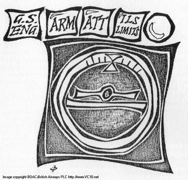
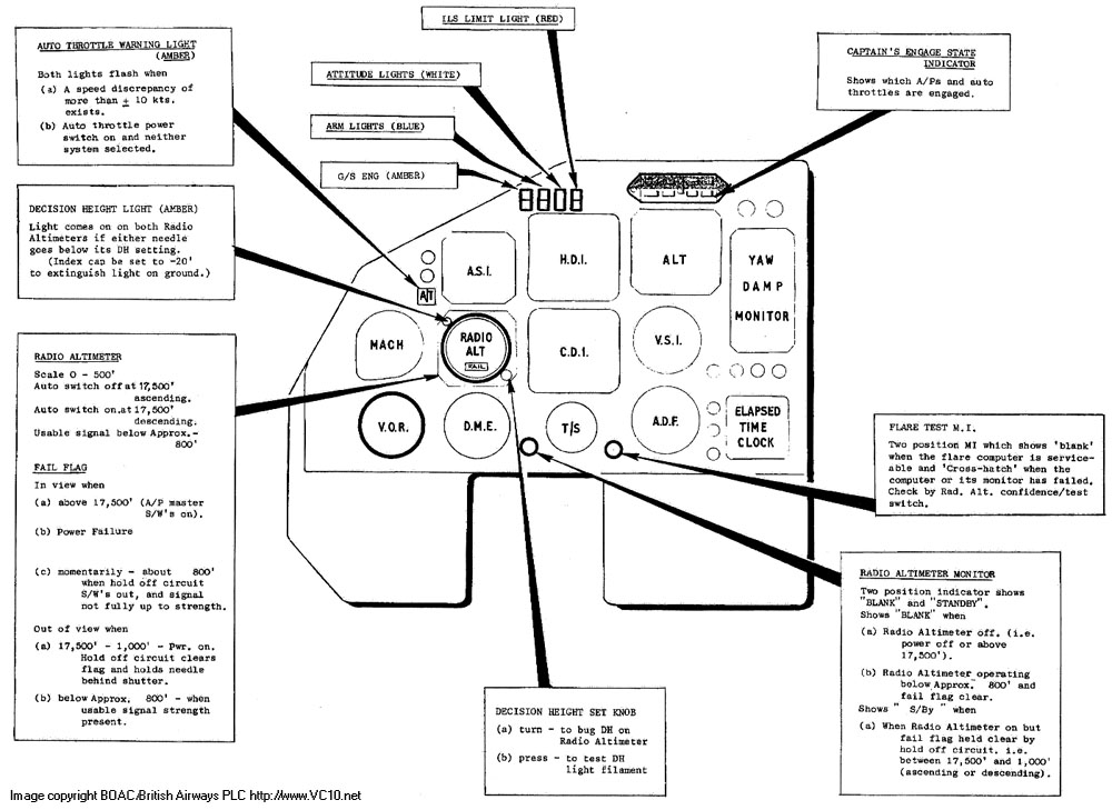
So what makes this a safe system? There are two main approaches to this problem: 1. use a system in triplicate and let this system vote on the results. As the chance of two systems failing in the same way is extremely small, two matching results and one non-matching one means that the odd one can be discounted. 2. use two systems which are self-monitoring. With this approach various parts of the system are constantly evaluating themselves (this is not needed with the triplicate system) and will report when there is something wrong. Upon receiving such a warning, the system will automatically switch control to the other half. This last type as developed by Elliot was chosen for the VC10. As mentioned before the main components were already in place but expansion of the system to include autoland capacity didn't start until the Super VC10 started flying. As mentioned above the flight deck of the VC10 received an additional radio altimeter, but this is not the only added item. The correct functioning of the system is partly shown by a row of sequence lights above the pilots Artificial Horizon. From left to right they are:
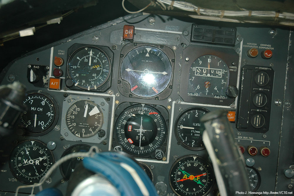
The autothrottle system is generally unchanged, but the performance is improved. The autothrottle warning lights have been moved to a position next to the airspeed indicators and consist of a large amber lamp with AT engraved (visible on photo at top of page).
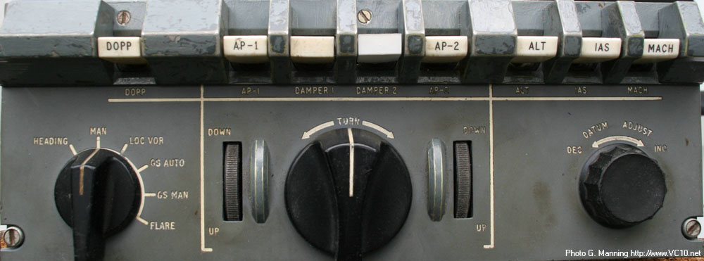
A new addition is the Boundary Limit Annunciator. This is a panel with four windows showing with 'hockey stick' symbols which boundary has been crossed when a divergence from the localizer or glide slope occurs. When the aircraft is more than a quarter dot away from the localizer the two hockey sticks on the relevant side show that the aircraft is not on the localizer. Similarly when the aircraft is more than one dot below the glideslope this will be shown by the bottom two hockey sticks illuminating. A combination of three hockey sticks can show a divergence in vertical and horizontal alignment and these indications should of course always correspond to the ILS bars on the Course Deviation Indicator (CDI). The Boundary Limit Annunciator is only mounted on the co-pilot's side. The last addition is the Engaged State Indicator. The co-pilot's version is shown on the right while the captain's version is a horizontal row of lights above the altimeter. This indicator shows which autopilot and autothrottle combination is in command at any stage of the flight. How does this all work then? The next step now we've got all the hardware sorted out is to look at the workings of the system during an approach and landing. For this we'll have a quick look at the options on the autopilot first. With reference to the photo below, the main switches are the white 'engage' switches at the top and the 'Mode Selector' switch at the left side of the panel. To get the aircraft set up for an automatic landing we need to have one of the two autopilots engaged in HEADING mode and aiming to intercept the ILS localizer signal. At circuit height (1500 feet) and decelerated to below 180 kt the autopilot can be set to LOC/VOR to intercept the localizer course which has been set on the CDI. One autothrottle is selected ON with the needed speed dialled in.
The autoland sequence starts after this first setup by engaging the other autopilot (no.1 should be activated first, then no.2) and selecting G/S AUTO on the mode selector. The autopilot will intercept the localizer signal at the set altitude and continue to track inbound to the runway. Once it intercepts the glide slope signal, the aircraft will then begin to descend on the approach path. At this point the first indicator above the artificial horizon (GS ENG) will come on, indicating that both autopilots are receiving glide slope signals.
Between 1000 feet and 800 feet the radio altimeters (RA) will become active and this is signalled by the RA needle becoming visible and moving to indicate the aircraft's descent. When the signal is good enough for the autopilots, the blue ARM lights will begin to flash to signal the pilots that they can now select LAND on the autopilot's mode selector. On the photo above this setting is labelled FLARE, this seems to be a discrepancy between the manuals and the panel as all the photos I can find show the 'FLARE' label. Once this mode has been selected the autopilot is set up for its autoland and the pilots now need to monitor its performance. To indicate this the ARM lights have changed to a steady on signal.
The aircraft is now at approximately 600 feet and following both localizer and glide slope signals with its flare computer armed. At 260 feet a signal from the radio altimeter will change the gearing for the localizer coupling to produce a tighter coupling. From this point on, if the aircraft should for some reason divert from its path, the ILS LIMIT light and the associated hockey stick indicators will come on. At 120 feet another trigger from the radio altimeter is sent out. At this point the glide slope signal is too narrow to follow accurately and the proximity to the transmitter is producing interference in the receiver. To overcome this the autopilot will switch to an attitude hold mode, fixing the aircraft's pitch so it will continue to descend with the vertical speed it was holding while following the glide slope. By doing this a shift in wind may cause the aircraft to end up slightly before or after the aiming point but in practice this error has turned out to be small. The localizer is still being tracked. In this phase the GS ENG light is out as the glide slope signal is now rejected, and the ATT light is on to show that the autopilot is in attitude hold mode.
At 50 feet above ground the radio altimeter will cause the flare computer to start the flare manoeuvre. The autothrottle will now close all the throttles and the flare computer will take over control of the pitch channel based on the RA height and the rate of change of this RA height. The yaw channel is released to the pilot so that the pilot can remove any drift and line up the nose of the aircraft with the runway centreline. At this point the attitude hold mode is no longer active and therefore the white ATT light goes off.
After this the aircraft should be rolling down the runway, the autopilot and autothrottle will now be manually disconnected and the flight crew will engage brakes and reverse thrust. To summarize this whole operation of multi-coloured lights: here is a diagram that shows the correct sequence. The red ILS LIMITS light is included in this diagram to illustrate the height band over which it can operate. Normally it will not be seen.
Something that is not on this page is the full sequence of tests and button presses that surrounds this whole procedure. Even without those the story gets complicated and readers may wonder why such a complex system of checks and lights was chosen. One reason was the state of electronics by then, many of these indications would now be combined into one screen or indicator but cockpit design had not reached that evolutionary step yet. The other reason was to do with certification. Britain had taken an important step towards regular use of autoland in 1961 by stating what the demands on such a system would be for certification purposes. These demands were quite broad but specified a level of safety and basically left it up to the manufacturer to figure out and demonstrate that the system would meet this demand. This was contrary to the US approach where a basic system was described and as long as you built something along those lines it would get certified. This enabled systems which needed less checks, but also systems that didn't have the failure survival of the VC10s system.
One of the challenges: integral bank I was recently sent this addition by George Sims, who used to work for Elliot Systems, the developer of the VC10 autopilot system: "In order to achieve the safety level needed for automatic landing it is necessary to hold on to the runway centre line very accurately. A stable control system requires a move towards the desired objective at a rate proportional to the distance from it. The traditional Localiser system used the obvious method of selecting a heading deviation from the known runway direction. The problem with this is that the aircraft is not necessarily moving in the direction in which it is pointing due to the wind. Also there is a delay in achieving the direction demanded, which reduces the stability of the system, and failure survival of the directional gyro and fluxgate transmitter is required. The alternative method is to just measure the rate of change of the beam error signal. Although the direction of the beam is very precise there is quite a high level of noise so the aircraft would be all over the place if the differentiated signal were not heavily smoothed. This results in an unacceptably unstable system. Another approach is to realise that the only way the aircraft is able to change its rate of movement through the beam is to apply a sideways force, which is achieved by banking. Integrating the bank angle therefore gives you a very good representation of the rate of moving through the beam. However any discrepancy between the lift angle and the bank angle as measured by the gyro will also be integrated so this has to be “washed out” to produce a fixed offset and then again to remove this. Clearly short term displacement rate is not sufficient but long term is easily available from smoothed differentiation of the beam error signal. At the time it was only possible to do what was possible with the available computing modules. These were a ‘lag’ to smooth signals and a band pass filter that was used for the yaw damper. Rather amazingly it was possible to combine these in such a way as to produce essentially perfect beam rate. The mathematics is rather complicated and not that obvious so will not be elaborated on here. Consequently it was possible to implement a high gain control system that held the aircraft very tightly on to the beam regardless of cross winds or even engine failure. This provided such a dramatic improvement in performance that the Government immediately classified the system after we put in a patent application for it, severely hampering progress unfortunately. Although I moved to a different part of Elliott Automation in 1965 I am aware that a new lateral coupler was developed using more modern DC amplifiers. This performed very successfully and reliably. Unfortunately funding was not available for a new flare computer although I believe the radio altimeter, over which EFA had no control, caused most of the problems. There is still major resistance to making automatic landings by pilots for the fairly obvious non technical reasons. " George's story provides a bit of insight into the theoretical and practical puzzles which had to be solved to provide a working, reliable system. Later, more modern electronics simplified this process and made autoland a very reliable tool but in 1968 we had not reached that point yet. Autoland in operation with BOAC From 1968 on the system was certified and ready for use. Crews were trained and slowly ground facilities were starting to turn up that delivered the needed accuracy. At the start not many runways were equipped for use with autoland but this changed in due course. Around the same time BEA was certifying their HS Trident for autoland for many of the same reasons that BOAC was busy with the Super VC10. As both these systems became operational one thing became clear though: when compared to BEA the number of times that BOAC was forced to resort to an autoland was quite small. BEA's Tridents flew to many of Europe's cities where weather could be problematic for large parts of the year while BOAC flew to Africa and Asia where fog was not a major issue on most days. Some destinations in the US and of course the UK benefitted from the system but to say that it was a much needed option would be overstating the issue. Initially reactions from the pilots were not always very positive. As captain A. Jackson wrote there were some captains who stated that as long as they were responsible for the aircraft, they would not rely on equipment to perform the landing. At first the BOAC requested pilots to use the system in good weather conditions to build confidence and experience but inevitably there were occasions where the system did not perform as expected, with erratic behaviour, disconnects and other issues. In his article on Radio Development on the VC10, Chris Mitchell explains that the autoland system was pretty tricky to keep operational. As he explains many schemes were raised to improve the system but in the end an evaluation of the expected system reliability made it clear that the system was too costly to continue with. So in the end the system was removed from the Super VC10s. Funnily enough, in a BOAC (BA by that time) flight manual updated to 1975 the pages describing the system are still there. Currently once a system is removed from an aircraft the manual will be changed to reflect this but perhaps this practice was not used in those days. For another look at the development of the system and the intricacies of keeping it operational, have a look at this article by Bruce Lumsden, who was involved in this development while working for the BLEU.
Even if the service life of the system wasn't as long as it could have been, it was still a major achievement. The British Pathé archive enables us to see what a fully automatic landing looked like on the VC10. Click this link to watch this clip on their website: More images
1-3. A sequence of three images showing the Captain's side of G-ASGK's cockpit with Autoland fitted, a graphic from the Flying Manual explaining the lights and controls, and a photo of the same panel as it is today on G-ASGC.
1-3. The same three images for the Co-Pilot's side of the cockpit, as shown previously on this page, but now together with the explanation for comparison.
|